 Maximize
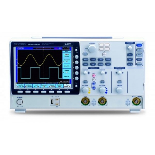
GW Instek GDS-3352
Digital Osciloscope GDS3352 2x350MHz 5GSa/s, 8-inch (Optional: Serial Bus Analysis Software for I2C / SPI/ UART, Power Analysis Software,In-rush)
Search
Manufacturers
Maximize Digital Osciloscope GDS3352 2x350MHz 5GSa/s, 8-inch (Optional: Serial Bus Analysis Software for I2C / SPI/ UART, Power Analysis Software,In-rush)
| GDS-3152 | GDS-3154 | GDS-3252 | GDS-3254 | GDS-3352 | GDS-3354 | GDS-3502 | GDS-3504 | |
| Vertical Sensitivity | ||||||||
| Input Channels | 2Ch+EXT | 4Ch+EXT | 2Ch+EXT | 4Ch+EXT | 2Ch+EXT | 4Ch+EXT | 2Ch+EXT | 4Ch+EXT |
| Bandwidth | DC~150MHz(-3dB) | DC~250MHz(-3dB) | DC~350MHz(-3dB) | DC~500MHz(-3dB) | ||||
| Rise Time | 2.3ns | 1.4ns | 1ns | 700ps | ||||
| Vertical Resolution | 8 bits | |||||||
| Vertical Resolution @ 1MΩ | 2mV~5V/div | |||||||
| Vertical Resolution @ 50/75Ω | 2mV~1V/div | |||||||
| Input Coupling | AC, DC, GND | |||||||
| Input Impedance | 1MΩ// 15pF | |||||||
| DC Gain Accuracy | ±(3% X |Readout| + 0.1div + 1mV) | |||||||
| Polarity | Normal, Invert | |||||||
| Maximum Input Voltage @1MΩ | 300Vrms, CAT I (300Vrms CAT II with GTP-151R/251R/351R/501R 10:1 probe ) | |||||||
| Maximum Input Voltage @50/75Ω | 5 VRMS max, CAT I | |||||||
| Offset Position Range | 2mV/div ~ 100mV/div : ±0.5V ;200mV/div ~ 5V/div : ±25V | |||||||
| Bandwidth Limit | GDS-3152/3154:20MHz (-3dB) | GDS-3252/3254: 20MHz/100MHz (-3dB) | GDS-3352/3354: 20MHz/100MHz/ 200MHz (-3dB) | GDS-3502/3504: 20MHz/ 100MHz/ 200MHz/ 350MHz (-3dB) | ||||
| Waveform Signal Process | Add, subtract, multiply, and divide waveforms, FFT, FFTrms | |||||||
| FFT: Spectral magnitude. | ||||||||
| Set FFT Vertical Scale to Linear RMS or dBV RMS, and FFT Window to Rectangular, Hamming, Hanning or Blackman-Harris.Integration*, Differentiation* *: App installation required | ||||||||
| Trigger | ||||||||
| Source | 2 CH model: CH1, CH2, Line, EXT | |||||||
| 4 CH model: CH1, CH2, CH3, CH4, Line, EXT | ||||||||
| Trigger Mode | Auto (supports Roll Mode for 100 ms/div and slower), Normal, Single Sequence | |||||||
| Trigger Type | Edge, Pulse Width(Glitch), Video, Runt, Rise & Fall(Slope), Alternate, Event-Delay(1~65,535 events), Time-Delay(Duration ,10ns~10s), | |||||||
| I²C, SPI, UART(optional) | ||||||||
| Runt: Trigger on a pulse that crosses one threshold but fails to cross a second threshold before crossing the first again. | ||||||||
| I²C (optional) | ||||||||
| Trigger on Start, Repeated Start, Stop, Missing ACK, Address (7 or 10 bit), Data, or Address and Data on I²C buses | ||||||||
| SPI (optional) | ||||||||
| Trigger on SS, MOSI, MISO, or MOSI and MISO on SPI buses | ||||||||
| UART (optional) | ||||||||
| Trigger on Tx Start Bit, Rx Start Bit, Tx End of Packet, Rx End of Packet, Tx Data, Rx Data, Tx Parity Error, and Rx Parity Error | ||||||||
| Trigger Holdoff Range | 10ns~10s | |||||||
| Coupling | AC, DC, LF rej., Hf rej., Noise rej. | |||||||
| Sensitivity | DC ~ 50MHz Approx. 1div or 10mV | |||||||
| 50MHz ~ 350MHz Approx. 1.5div or 15mV | ||||||||
| EXT Trigger | ||||||||
| Range | ±15V | |||||||
| Sensitivity | DC ~ 150MHz Approx. 100mV ;150MHz ~ 250MHz Approx. 150mV 250MHz ~ 350MHz Approx. 150mV ;350MHz ~ 500MHz Approx. 200mV | |||||||
| Input Impedance | 1MΩ±3%, ~16pF | |||||||
| Horizontal | ||||||||
| Time base range | 1ns/div ~ 100s/div (1-2-5 increments;GDS-3502/3504:1-2.5-5 increments); ROLL : 100ms/div ~ 100s/div | |||||||
| Pre-trigger | 10 div maximum | |||||||
| Post-trigger | 1,000 div | |||||||
| Time base accuracy | ±20 ppm over any ≧1 ms time interval | |||||||
| X-Y Mode | ||||||||
| X-Axis Input | Channel 1; Channel 3 | |||||||
| Y-Axis Input | Channel 2; Channel 4 | |||||||
| Phase Shift | ±3° at 100kHz | |||||||
| Signal Acquisition | ||||||||
| Real Time Sample Rate | 2.5GSa/s | 5GSa/s | 2.5GSa/s | 5GSa/s | 5GSa/s | 5GSa/s | 4GSa/s | 4GSa/s |
| ET Sample Rate | 100GSa/s maximum for all models | |||||||
| Record Length | 25k points/ channel | |||||||
| Acquisition Mode | Normal, Average, Peak detect, High resolution, Single | |||||||
| Normal: Acquire sampled values. | ||||||||
| Average: From 2 ~256 waveforms included in average. | ||||||||
| Peak Detect: Captures glitches as narrow as 2 ns at all sweep speeds | ||||||||
| Hi Res: Real-time boxcar averaging reduces random noise and increases vertical resolution. | ||||||||
| Cursors and Measurement | ||||||||
| Cursors | Amplitude, Time, Gating available | |||||||
| Automatic Measurement | 28 sets: Vpp , Vamp , Vavg , Vrms , Vhi , Vlo , Vmax , Vmin , Rise Preshoot/ Overshoot , Fall Preshoot/Overshoot, Freq , Period , Rise Time , Fall Time , Positive Width , Negative Width , Duty Cycle, Phase angle, and eight different delay measurements (FRR, FRF, FFR, FFF, LRR, LRF, LFR, LFF) | |||||||
| Cursors measurement | Voltage difference between cursors ( ∆V) Time difference between cursors ( ∆T) | |||||||
| Auto counter | 6 digits, range from 2Hz minimum to the rated bandwidth | |||||||
| Power Measurements (option) | ||||||||
| Power Quality | VRMS, VCrest Factor, Frequency, IRMS, ICrest Factor, True | |||||||
| Measurements | Power, Apparent power, Reactive power, Power factor, Phase angle. | |||||||
| Harmonics | Freq, Mag, Mag rms, Phase, THD-F, THD-R, RMS | |||||||
| Ripple Measurements | V ripple ,I ripple | |||||||
| In-rush current | First peak, Second peak | |||||||
| Control Panel Function | ||||||||
| Autoset | Single-button, automatic setup of all channels for vertical, horizontal and trigger systems, with undo autoset | |||||||
| Auto-Range | Allow users to quickly move from test point to test point without having to reset the oscilloscope for each test point | |||||||
| Save Setup | 20 set | |||||||
| Save Waveform | 24 set | |||||||
| Display System | ||||||||
| TFT LCD Type | 8" TFT LCD SVGA color display | |||||||
| Display mode | YT ;XY | |||||||
| Display Resolution | 800 horizontal × 600 vertical pixels (SVGA) | |||||||
| Interpolation | Sin(x)/x & Equivalent time sampling | |||||||
| Waveform Display | Dots, vectors, variable persistence, infinite persistence | |||||||
| Display Graticule | 8 x 10 divisions | |||||||
| Display Brightness | Adjustable | |||||||
| Waveform capture rate | 3500 waveform /sec real time | |||||||
| Interface | ||||||||
| RS-232C | DB-9 male connector | |||||||
| USB Port | 2 sets USB 2.0 High-speed host port ; 1 set USB High-speed 2.0 device port | |||||||
| Ethernet (LAN)Port | RJ-45 connector, 10/100Mbps | |||||||
| SVGA Video Port | DB-15 female connector, monitor output for display on SVGA monitors | |||||||
| GPIB | GPIB to USB Adapter (GUG-001 Option) | |||||||
| Go/NoGo BNC | 5V Max/10mA TTL Open collector output | |||||||
| Internal flash disk | 64MB | |||||||
| Kensington Style Lock | Rear-panel security slot connects to standard Kensington-style lock. | |||||||
| Line output | 3.5mm stereo jack for Go/NoGo audio alarm | |||||||
| Power Source | ||||||||
| Line Voltage range | AC 100V ~ 240V, 48Hz ~ 63Hz, Auto selection | |||||||
| operation environment | Temperature: 0°C to 50°C. Relative Humidity ≤ 80% at 40°C or below; ≤ 45% at 41°C ~ 50°C | |||||||
| Miscellaneous | ||||||||
| Multi-language menu | Available | |||||||
| On-line help | Available | |||||||
| Time clock | Time and Data, Provide the Data/Time for saved data | |||||||
| Dimensions & Weight | 400(W) X 200(H) X 130(D)mm, approx 4 kg | |||||||

564,57 €

921,27 €

977,85 €

485,85 €

981,54 €

981,54 €

1 659,27 €

2 521,50 €

1 350,54 €

1 842,54 €

1 599,00 €

2 457,54 €

814,26 €

970,47 €

3 321,00 €

2 548,56 €

1 842,54 €

276,75 €

366,54 €

338,25 €

306,27 €

404,67 €

392,37 €
404,67 €


1 100,85 €

4 551,00 €

719,55 €

355,47 €

Contact us


